


Murata Noise Suppression for MIPI C-PHY
Smartphone displays are becoming larger with higher resolutions as the volume of the information handled goes up. As a result, the data volume of video signals sent to displays is also increasing. A differential transfer interface called MIPI D-PHY has been used to efficiently transfer these signals. But now, MIPI C-PHY is increasingly being used as an interface that can transfer data at even higher speeds. The MIPI C-PHY transfer system differs from the previous one, D-PHY, so different noise filters are needed. Murata highlights the noteworthy features of MIPI C-PHY noise suppression and the noise suppression products commercialized for MIPI C-PHY.
MIPI Diagram

Meaning of MIPI C-PHY
MIPI C-PHY is a standard for data transfer inside mobile equipment, established by the standards organization MIPI Alliance. C-PHY has a signal speed of 5.7Gbps per lane, while D-PHY has a maximum speed of 2.5Gbps per lane/
The M-PHY standard has also been created as a successor to D-PHY, but the C-PHY standard has been created as a bridge standard between D-PHY and M-PHY. D-PHY uses typical differential transfer lines comprising two pins per lane, while C-PHY uses more complex differential transfer lines comprising three pins per lane.
PHY Chart

C-PHY benefits
• C-PHY transfers data over three lines → Data transfer speed is increased (Signal frequency is the same as D-PHY).
• There is no clock line → Space savings over existing designs.
MIPI C-PHY Signal Transfer

• Three lines of data are transferred as one lane
• There is no clock line.
• The values of the three lines (A, B, and C) will become High, Middle, or Low.
• The three lines will each have different values. (Two or more lines cannot be in the same condition.)
• Reception is by the differential of every two lines (AB, BC, and CA)
• Each line is matched to 50Ω, and 100Ω differentially.
Noise filters required in MIPI C-PHY
In conventional MIPI D-PHY, it is necessary to remove common mode noise to avoid having an adverse effect on differential signals. To achieve this, two-line common mode noise filters are used. However, MIPI C-PHY transmits differential signals using three signal lines, so typical common-mode noise filters cannot be used as-is.
One possible method is to combine three common mode noise filters (Diagram below, left side). But this has a large effect on the signals, so sufficient common mode noise suppression effects cannot be expected. As a result, MIPI C-PHY noise suppression requires a common mode noise filter that supports three-line differential signals.
When using a three-line common mode noise filter that magnetically couples the three lines internally, circuit simulation is used to check whether the signals can be transferred effectively.
Using a two-line filter, the transfer waveform is disturbed. But when a three-line common mode noise filter was used, Murata found the signals are transferred without disturbance to the waveform.
Noise Filters Diagram

Waveform verification by simulation

Comparison of 2-line and 3-line CMCC
Common-mode noise filters developed for MIPI C-PHY
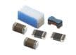
Murata's NFG0NCN_HL3 series are noise filters that were developed as a countermeasure for common-mode noise in MIPI C-PHY. Within their miniature size of 0.90mm x 0.68mm, three lines are magnetically coupled in the configuration of these common mode noise filters.
NFG0NCN162HL3 has an insertion loss peak between 900MHz and 3GHz. This feature makes it suitable to prevent noise interference to the carrier frequency.
NFG0NCN Specifications

Effectiveness of NFG0NCN_HL3
Murata's NFG0NCN_HL3 series was used to check the effectiveness of the noise countermeasures. The chart below compares the noise spectrum radiating from the transfer lines before and after filter insertion.
By inserting the NFG0NCN162HL3, the conspicuous noise below 2GHz could be greatly reduced.
Next, a near magnetic field probe was used to observe the degree to which the noise distribution on the PCB would change.
In the locations after the filter insertion portion, the distribution of the noise was reduced and the amount of 0.8GHz or 1GHz noise reduction was especially remarkable. (Figure 1, below)
Noise countermeasure effectiveness was checked for the NFG0NCN_HL3 series of common-mode noise filters for MIPI C-PHY. (Figure 2, below)
Figure 1

Noise countermeasure effectiveness of the common-mode noise filter for MIPI C-PHY
Figure 2

Noise countermeasure effectiveness of the common-mode noise filter for MIPI C-PHY (2)
Verification of signal waveform
By inserting the NFG0NCN_HL3 series into the signal lines, Murata checked whether this had an adverse influence on the signal waveform. Murata confirmed the eye pattern of the signal satisfied the specifications of the template.
Signal Transfers

A check of the signal transfer characteristics of the common-mode noise filters for MIPI C-PHY
Skew Improvement Effectiveness
Common-mode noise filters are also effective in improving the skew of differential signal lines.
Skew refers to the shift of the signal propagation time between multiple signal lines. Skew is generated by the asymmetric quality of the circuits and other factors. This shifting of the respective signals leads to changes of the signal potential difference received at the receiving side. This process reduces the operating margin of the circuits.
Using a common-mode filter in a differential signal circuit that has skew will remove the common-mode component produced by the skew, and the skew will be improved. (Skew Diagram below)
Skew Improvement Effectiveness of Common-Mode Noise Filters
The use of common-mode noise filters can be expected to be effective in improving the skew of transfer signals. Since the skew (time lag between signals) is propagated by common mode, the use of common-mode noise filters can improve the skew.
Skew Diagram

Summary
• MIPI C-PHY uses a three-line transfer that differs from the differential transfer lines used up until now. As a result, the existing two-line common mode noise filters cannot be used with MIPI C-PHY.
• Murata's NFG0NCN_HL3 series is a three-line common mode noise filter designed with the precondition of use with MIPI C-PHY.
• Use of the NFG0NCN_HL3 series permits the reduction of the common-mode noise that is transferred to MIPI C-PHY and suppresses to a low level the deterioration of signal quality.
• The use of common-mode noise filters can also improve the skew of the signals.
SimSurfing Tool

Community Forum
Murata Community Forum provides searchable content with various discussion topics, popular blogs, and articles. The Murata broad market support team holds regular reviews to discuss open issues, allowing inquiries to be answered in a timely manner. The forum content is freely accessible to the public. However, users must log in to post questions or answers. Registration is free of charge.
Learn More
Murata EMI雜訊抑制
為工程師提供完整的支援,包括產品 & 設計模擬軟件解決方案。
Related Products

Murata NFG共模雜訊濾波器
提供100mA額定電流、19至29dB插入損耗範圍及10MΩ絕緣電阻。